Passive Preamp

Overview  Circuit description  Protocol  Parts/PCB
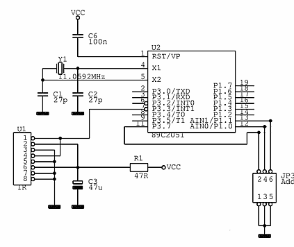
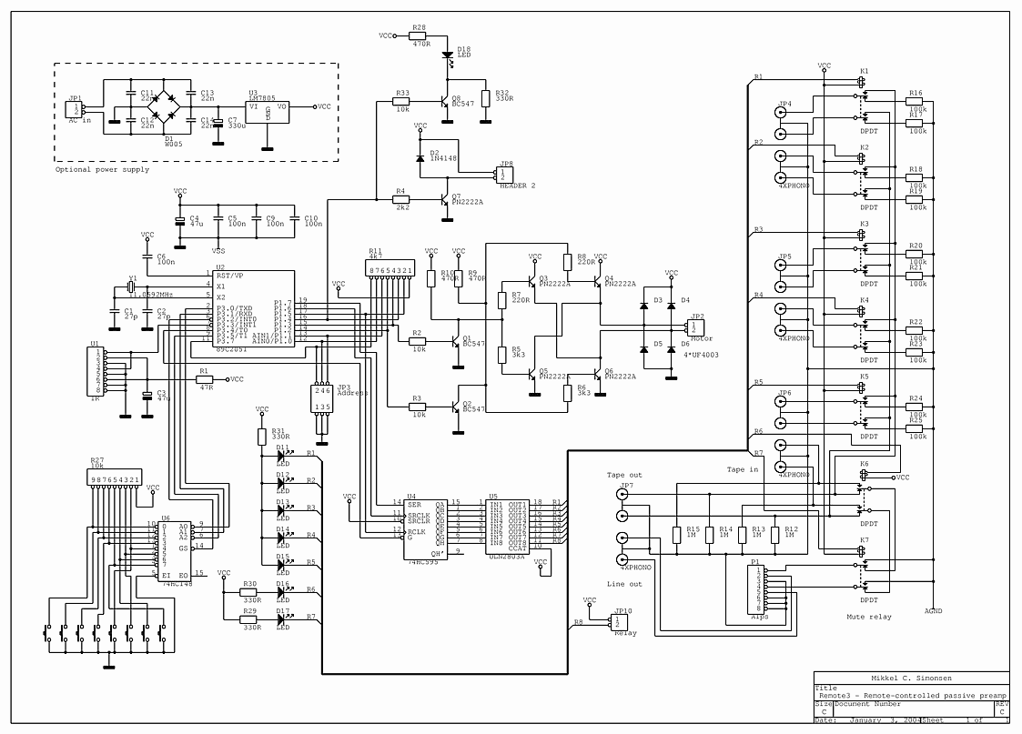
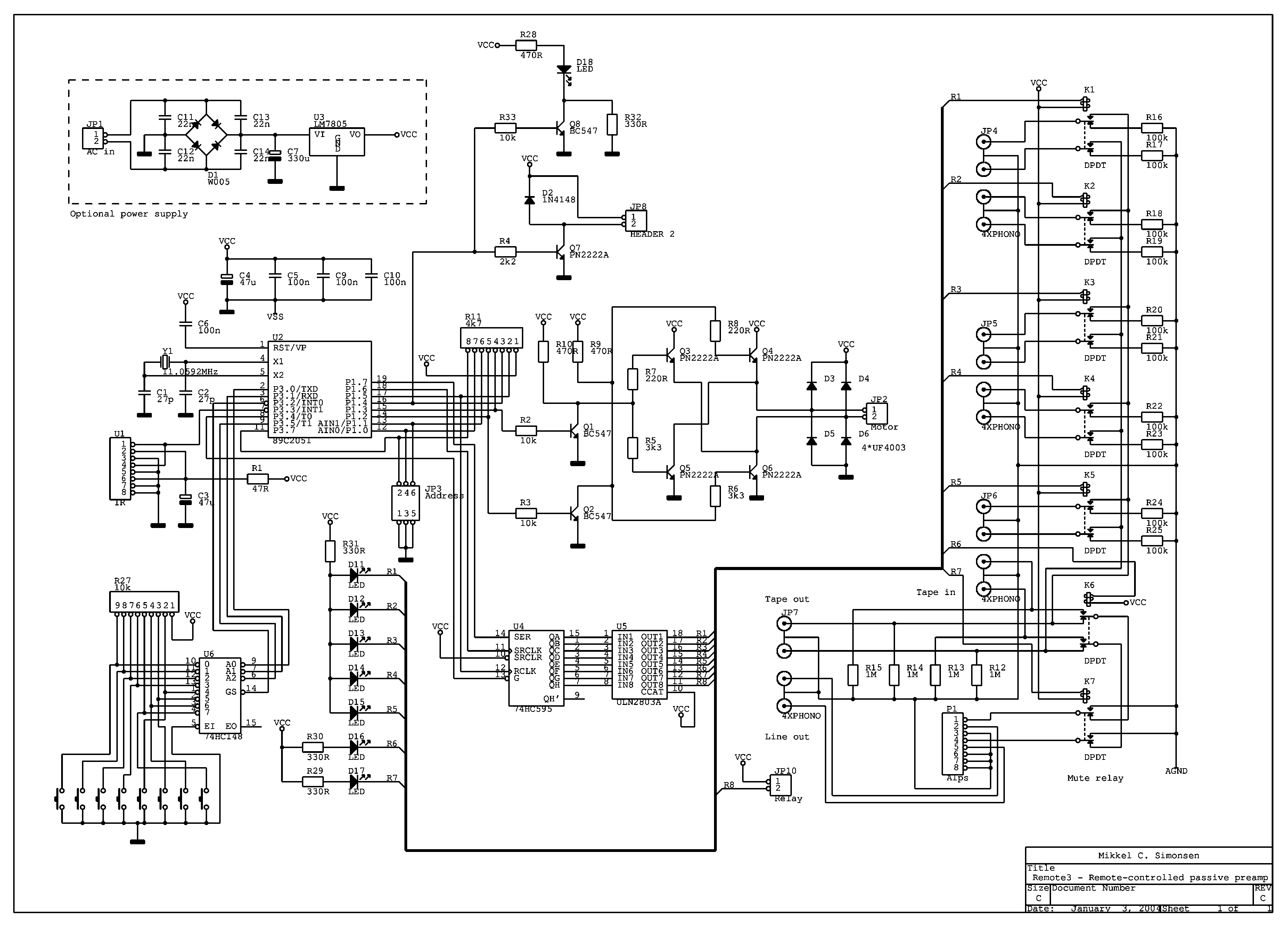
Most of the circuit is identical to the small remote control board as mentioned, so if you have read 
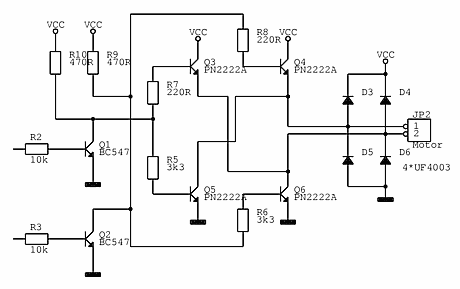
the description of that circuit, a lot of the text below will look familiar :-)

The circuit uses an IR receiver chip to receive the IR signal from the remote. The chip includes a bandpass filter and a demodulator, so the output is a logic signal.

The signal is then processed by an Atmel 89C2051 chip that decodes the remote signal and controls the volume pot and relays.
 
Controller schematic

Keyboard encoder
The controller section is more or less a standard 8051 circuit - the controller chip is basically an updated Intel 87C51 with less pins. Please note that the controller chip has to be programmed. If you buy an AT89C2051 chip it's "empty", so the circuit won't do anything...

The output from the IR receiver is connected to one of the chip's two interrupt inputs. The other input, that was used for a power switch on the small board, is connected to the "GS" output of a priority encoder chip that's used as a "keyboard controller" here. That means the chip can be "put to sleep" most of the time, because signals on those two pins can wake it up.

The GS output on the keyboard controller chip is activated when any of the 8 buttons are pressed. The resistor network R27 is there to make sure that the inputs of the encoder chip don't float when the buttons are de-pressed.

The address jumper JP5 is used for selecting the RC5 address. Read more in the "Protocol" section.

BTW, in case you're wondering - 11.0592MHz IS a standard crystal frequency... :-)
Relay driver schematic

Relay driver circuit
This circuit is used for controlling the power relay (if used). There is no power relay on the board, but the output can be used to control a relay in the power amp for instance. According to different datasheets the transistor is rated for somewhere between 0.5 and 0.8A.

Most standard relays draw less than 0.1A, so connecting more than one relay shouldn't be a problem. 5 or 6V relays can be used.

The relays in the input selector/mute circuit are controlled by a serial input shift register. That is used to save output pins on the microcontroller. Instead of 8 pins three are enough. The relays are switched using an ULN2803 driver chip. It is basically 8 darlington transistors in a single package, which saves some space and soldering. There is an un-used relay output on the driver chip. It could be used for B+ delaying or other purposes.
 
Motorpot driver schematic
This part controls the volume pot.

The output pins on the microcontroller are high on reset/power-up, so the motor has to be off with both control inputs high.

The two BC547 transistors Q1 and Q2 make sure the base drive for the output transistors is off on power-up.

When the volume pot has to be moved, the base of either Q1 or Q2 is driven low switching off the transistor. This enables two of the output transistors to switch on. Q3 and Q5 switch on for one direction and Q4 and Q6 for the other direction. If both Q1 and Q2 are switched off at the same time strange things may happen. So that mode of operation is not supported by the standard software ;-)

Here is the complete schematic. I have made both a low resolution file (72dpi) for viewing, and a higher resolution file (200dpi) for printing.

Overview  Circuit description  Protocol  Parts/PCB


Home

Comments? Questions? Just send me an e-mail!

MailMail: mcs@post5.tele.dk