 |
|
 |
|
|
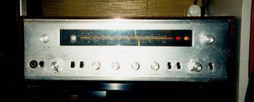
Schematics I recently bought a Sansui 500. I bought it as non-working and that was how I received it. When I tested it the indicator lights worked, and the tube heaters were on. I checked the B+ voltage - there wasn't any. The electrolytics in the powersupply didn't look to good, and the 2 Ohm resistor feeding the main caps looked like it had been on fire. The schematic is glued to the lid, but is very small. I carefully removed it and scanned it, if someone else has a use for it. After replacing the three caps in the power supply (I used three 50+50µF LCR caps and a 33µF), and fitting a new 2 Ohm resistor, i tested the receiver again. This time the B+ was about right (250V), but the new resistor started smoking as soon as the tubes got hot, so I quickly switched off again. Now i tried to measure the voltage across the resistor. It turned out that the current was about 500mA - no wonder the resistor got hot. The B+ winding has a 0.25A limit according to the schematic... Next I removed the power amp tubes (4 * ECL82/6BM8), and turned the receiver back on. Now everything was close to normal. The current was less than 200mA (which is still a lot I guess), and the tuning indicator came on. I tried to connect an amp to the tape outputs and the tuner played just fine. In both mono and stereo. Now I think I am getting closer to the real problem. Leaky oil coupling caps. The grid voltage on the power tube sockets was positive! It should be -19V. The caps in the preamp were also leaky. The plate voltages were only around half of what they should be, and there was 20V DC across the balance pot. I guess I will have to replace about 10 caps. This is how far I have come now. I have ordered new polypropylen caps, and some 470µF 250V caps for the powersupply. They are the same size as the original 200µF 180V caps. To be continued... |
|
|
After replacing 12 of the oil caps and about 10 electrolytics, i tested the receiver once more. Now
the current going through the 500 Ohm resistor in the PSU was about 80mA. The bias was now about -15V.
I set it to -20V to be on the safe side. It should be -19V according to the schematic. Time for another test with the power tubes installed! This time it went a lot better. The B+ was correct (255V) with the powertubes installed, and the bias stayed at -20V. And this time nothing smoked. I replaced one of the load resistors with a speaker, and it played! I connected a signal to the AUX input, but only one of the channels worked. Next I tried the Tape Mon input. That worked after fiddling with the Tape Monitor switch a bit. It seems there is quite a bit of dirt on the switches, so they are all a bit flaky. I guess some contact cleaner should be able to fix this. The amp sounds very good, but it seems the gain is very high in the preamp. When playing CDs or using the FM MPX function I can't get the volume control past 1 (the max. is 9). Is the gain really supposed to be that high? The volume is a bit lower when playing FM mono, but it is still quite loud at 1. |
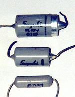 Suzuki oil-caps 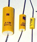 And the replacements from RS |
|
Schematics Here is the scan of the Sansui 500 schematic. I split it in four parts. I have made two versions of each file. One high resolution (600dpi) for printing and a lower resolution grayscale file for viewing. The high-res files are quite large, so use an image viewer for viewing/printing them. Netscape sometimes crashes when displaying large gif files... Low res: Tuner/powersupply Multiplexor Amplifier Symbols High res: Tuner/powersupply Multiplexor Amplifier Symbols |
|
|
Comments? Questions? Just send me an e-mail! |
|