 |
||
|
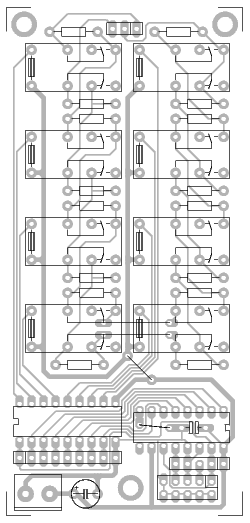
The circuit shown on this page is a pot (potentiometer) made using relays and resistors. 8 relays and
16 resistors are used to make a 256-step linear pot. By selecting only some of the steps you can make
a pot with any taper needed (log, rev. log etc.). |
||
The circuit also shows a possible control circuit. The two resistors in each stage should have the same values. The resistors at the top of the drawing (R1 and R16) should be the smallest value and the ones at the bottom (R8 and R9) should be the largest value. The relay board can be controlled either through the 10-pin header, which is an SPI port, or the 9-pin header can be used for parallel control. The circuit runs on 5V DC. The relays are standard DIL relays. Component placement drawing PDF Track side PDF Gerber and drill files zip I will add descriptions of the control section later. |
